Source Geometry
- The geometry of the source representation follows the Aki & Richards (1980, 2002) convention. The strike of the fault plane (or any segment of it), representing the azimuth of the fault's projection onto the surface, is measured from North (positive in clock-wise direction), the dip of the fault (or individual fault segments) is measured downward from the surface to the fault in the vertical plane perpendicular to the strike. The strike direction is defined such that the dip-angle is smaller than 90° (i.e. using the right-hand rule with the thumb oriented in postive strike direction, your hand rotates downward from the horizontal into the fault plane by an angle less than 90°).
- We adopt a default viewing angle of (strike + 105°) to display the 3D-geometry of the source model, although we make exceptions for a number of events to either optimize the image or to honor "standard" viewing angles that have been used repeatedly in the past for specific cases (e.g. the 1992 Landers earthquake).
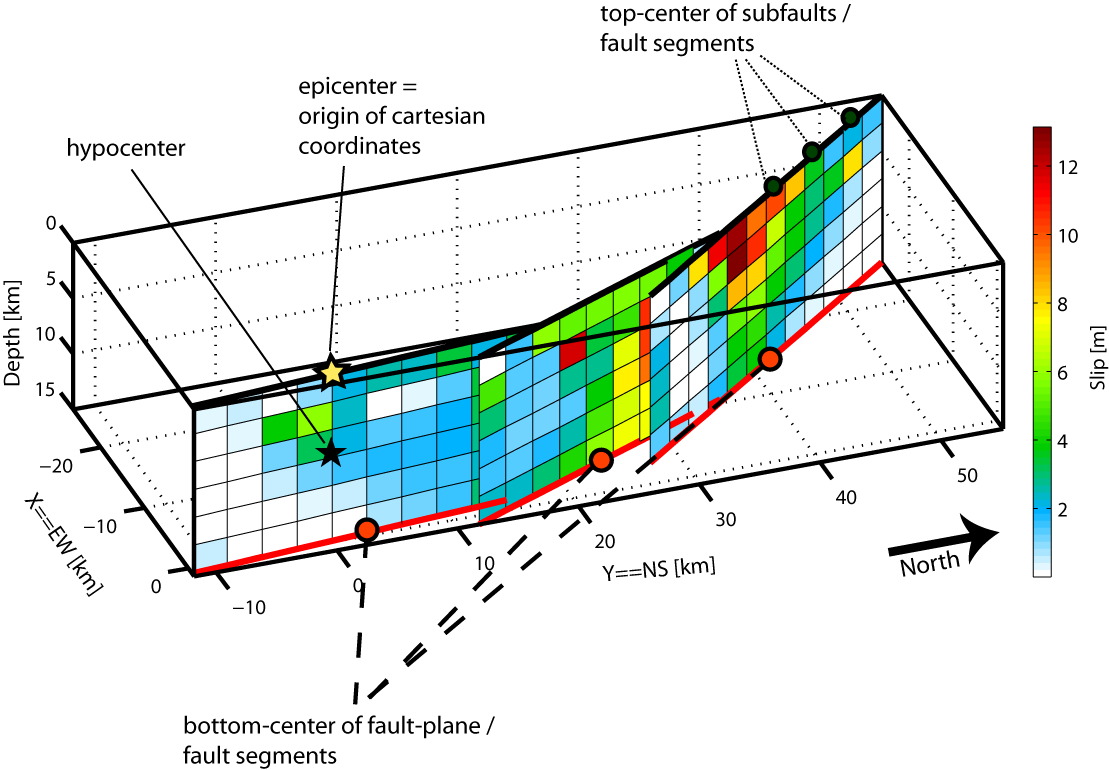
- The geometrical representation uses the top-center of each fault segment and each subfault as reference; latitude, longitude and depth for each segment/subfault are provided as well as X (EW, positive toward E) and Y (NS, positive toward N) coordinates with origin at the epicenter, computed using UTM-coordinates based on the UTM-zone of the epicenter. Hence, geometrical biases or small deviations from other sources or published images may occur if the epicenter is located close to a border of an UTM zone.
-
For most multi-segment events in the database, latitude/longitude information
for the individual segments had to be extracted from published images or was estimated from incomplete data.
The 3D-representation of these rupture models is hence only approximate and should be carefully checked for
subsequent studies in which geometrical accuracy at a 10-meter-scale (or smaller) is needed.
Multi-segment models in the database do not necessarily correspond to events with explicit rupture of multiple fault-segments. Sometimes, multiple segments has been defined to construct complicated fault-geometry; for instance, varying strike, dip and/or rake angles.
-
We adopt the standard sign convention for the rake angles:
rake ~ 0 deg for left lateral strike-slip,
rake ~ +/- 180 deg for right lateral srike-slip,
rake is positive for reverse dip-slip, and
rake is negative for reverse dip-slip. - The figure below summarizes the geometrical source representation: